Hartley Image Rejection Mixer

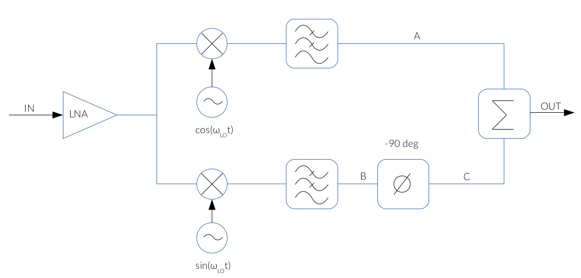
Fig. 1: Hartley architecture block diagram
Assume that the incoming signal is the sum of the desired signal and the image frequency:
$$ v_{ RF }( t ) = V_{ SIG } · cos( \omega_{SIG} · t ) + V_{IM } · cos( \omega_{IM} · t ) \tag{1} $$
The incoming signal is downconverted to IF and low-pass filtered to remove the higher frequency components generated by the downconversion. Thus, since the mixer acts as a time domain multiplication, the IF waveforms at A and B are:
$$ IF_A( t ) = { { A_{SIG} } \over { 2 } } · cos( (\omega_{SIG} - \omega_{LO}) · t ) + { { A_{IM} } \over { 2 } } · cos( (\omega_{LO} - \omega_{IM}) · t ) \tag{2} $$
$$ IF_B( t ) = -{ A_{SIG} \over 2 } · sin( (\omega_{SIG} - \omega_{LO}) · t ) + { A_{IM} \over 2 } · sin( (\omega_{LO} - \omega_{IM}) · t ) \tag{3} $$
Provided that sin(α) = cos(α – π/2):
$$ IF_B( t ) = -{ A_{SIG} \over 2 } · cos( (\omega_{SIG} - \omega_{LO}) · t - {\pi \over 2} ) + { A_{IM} \over 2 } · cos( (\omega_{LO} - \omega_{IM}) · t - {\pi \over 2} ) \tag{4} $$
The lower branch, B, is 90° phase shifted, so at the output we get:
$$ IF_C( t ) = -{ A_{SIG} \over 2 } · cos( (\omega_{SIG} - \omega_{LO}) · t - \pi) + { A_{IM} \over 2 } · cos( (\omega_{LO} - \omega_{IM}) · t - \pi) \tag{5} $$
$$ IF_C( t ) = { A_{SIG} \over 2 } · cos( (\omega_{SIG} - \omega_{LO}) · t)- { A_{IM} \over 2 } · cos( (\omega_{LO} - \omega_{IM}) · t ) \tag{6} $$
At the output, the voltage waveforms IFA(t) and IFC(t) are added, so we get:
$$ IF_{ OUT }( t ) = IF_A( t ) + IF_C( t ) = A_{SIG} · cos( (\omega_{SIG} - \omega_{LO}) · t ) \tag{7} $$
As seen, the sum cancels out the signal from the image frequency.
Image Rejection vs Circuit Impairments
The image cancellation relies on the perfect symmetry of the circuit. In practice, the image rejection is usually about 35dB (without dynamic calibration). In order to quantify this effect, we may express the LO waveforms as follows:
Lower mixer:
$$LO_1 = sin( \omega_{LO} · t ) \tag{8} $$
Upper mixer:
$$ LO_2 = (1 + \epsilon)sin( \omega_{LO} · t + \Delta·\theta ) \tag{9} $$
where the lower mixer shows amplitude (ε) and phase (ΔΘ) impairments.
Under the assumption that the received signal has the form:
$$ V_{RF}( t ) = A_{SIG} · cos( \omega_{RF} · t + \phi_{SIG}) + A_{IM} · cos ( \omega_{IM} · t + \phi_{IM} ) \tag{10} $$
The voltage waveform at A (see Fig. 1) is:
$$ IF_A( t ) = { A_{SIG} \over 2} · ( 1 + \epsilon ) · cos( (\omega_{RF} - \omega_{LO})· t + \phi_{SIG} + \Delta · \theta ) + { A_{IM} \over 2} · ( 1 + \epsilon ) · cos( (\omega_{IM} - \omega_{LO})· t + \phi_{IM} + \Delta·\theta ) \tag{11} $$
whereas the waveform at B and is still the same as in Eqs. (5) and (6)
At the end of the mixer, we have the sum of the xA(t) and xC(t) voltages (see Eq. (12)). We see that the local oscillator impairment affects both to the desired signal and the image.
$$ IF_{OUT}(t) = \color {blue} {x_{SIG}( t )} + \color {red} {x_{IM}( t )} = $$
$$ = \color {blue} { {A_{SIG} \over 2} · ( 1 + \epsilon ) · cos( (\omega_{RF} - \omega_{LO}) · t + \phi_{SIG} + \Delta·\theta) + {A_{SIG} \over 2} · cos( (\omega_{RF} - \omega_{LO} ) · t + \phi_{SIG} )} + $$
$$ + \color {red} { {A_{IM} \over 2} · (1 + \epsilon) · cos( (\omega_{IM} - \omega_{LO}) · t + \phi_{IM} + \Delta·\theta) - { A_{IM} \over 2} · cos( (\omega_{IM} - \omega_{LO}) · t + \phi_{IM}) } \tag{12} $$
In order to quantify the image rejection, we define the image rejection ratio (IRR) as the ratio of the power of the signal and the image at the output of the mixer. From Eq. (12), we use the following expression to calculate the average power:
$$ \langle a·cos(\omega · t + \alpha) + b · cos(\omega · t) \rangle = { {a^2 + 2 · a · b · cos(\alpha) + b^2} \over 2} \tag{13} $$
Using Eq. (13), the average power of the desired signal is given by:
$$ x_{SIG}( t ) = {A_{SIG} \over 2} · ( 1 + \epsilon ) · cos( (\omega_{RF} - \omega_{LO}) · t + \phi_{SIG} + \Delta·\theta) + {A_{SIG} \over 2} · cos( (\omega_{RF} - \omega_{LO}) · t + \phi_{SIG} ) $$
$$ \Longrightarrow P_{sig}^{average} = { {A_{SIG}^2 · (1 + \epsilon)^2} \over 4^2} + 2 · { {A_{SIG}^2 · (1 + \epsilon)} \over 4^2} · cos( \Delta·\theta ) + {A_{SIG}^2 \over 4^2} \tag{14} $$
Similarly, for the contribution coming from the image frequency:
$$ x_{IM}( t ) = {A_{IM} \over 2} · (1 + \epsilon) · cos( (\omega_{IM} - \omega_{LO}) · t + \phi_{IM} + \Delta·\theta) - { A_{IM} \over 2} · cos( (\omega_{IM} - \omega_{LO}) · t + \phi_{IM})$$
$$ \Longrightarrow P_{IM}^{average} = { { A_{SIG}^2 · (1 + \epsilon)^2 } \over 4^2} - 2 · { { A_{SIG}^2 · (1 + \epsilon) } \over 4^2} + {A_{SIG}^2 \over 4^2} \tag{15} $$
Since the IRR is the ratio between the signal and the image signals, we have:
$$ IRR^{n.u.)} = {P_{SIG}^{average} \over P_{IM}^{average} } = {A_{SIG}^2 \over A_{IM}^2}· { (1 + \epsilon)^2 + (1 + \epsilon)·cos(\Delta·\theta) + 1 \over (1 + \epsilon)^2 - (1 + \epsilon)·cos(\Delta · \theta) + 1 } \tag{16} $$
$$ IRR = 10·log_{10} \left( {A_{SIG}^2 \over A_{IM}^2}· { (1 + \epsilon)^2 + (1 + \epsilon)·cos(\Delta·\theta) + 1 \over (1 + \epsilon)^2 - (1 + \epsilon)·cos(\Delta · \theta) + 1 } \right) \tag{17} $$
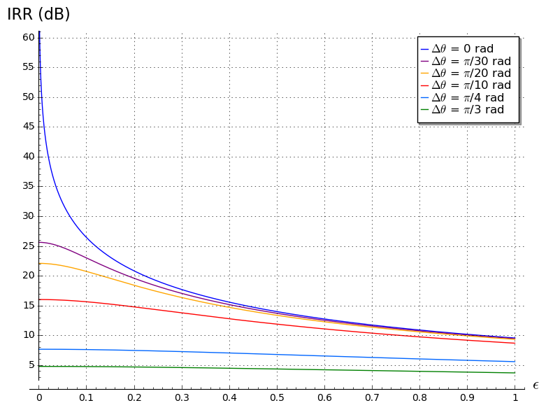
At the light of Eqs. (16) and (17), it is possible to calculate the IRR in terms of the amplitude and the phase mismatches of the LO signal [1]. Fig 2 plots Eq (17) for different values of ε and Δθ and it shows that the mismatch between the LO waveforms should be near π /30 (6°) for achieving a IRR = 25dB

Fig. 2: IRR vs amplitude and phase LO mismatch
See also
References
[1] Behzad Razavi, RF microelectronics, 2011