SSB Mixer
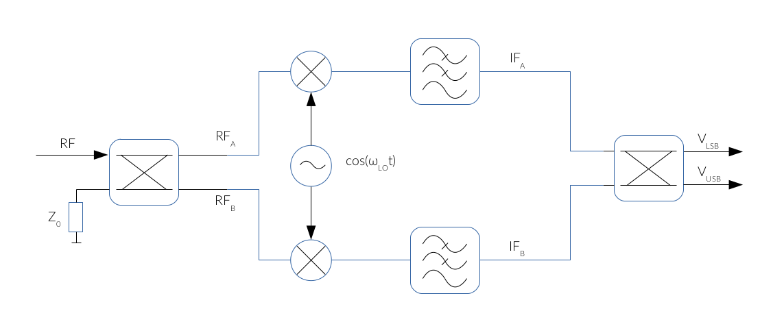
An interesting modification of the Hartley architecture is the single sideband mixer (SSB) described in [4]. The use of 90° hybrids makes possible to get both sides of the spectrum fLSB and fUSB at IF frequency in two different ports at the output:

Fig. 1: SSB mixer
The working principle of this mixer can be analyzed using the small signal analysis. As it was seen before, the signal coming from the RF port is the sum of the LSB and the USB spectral components:
$$ v_{ RF }( t ) = V_{ USB } · cos( \omega_{USB} · t ) + V_{ LSB } · cos( \omega_{LSB} · t ) \tag{1} $$
Provided that,
$$ \omega_{USB} = \omega_{LO} + \omega_{IF} \tag{2} $$
and,
$$ \omega_{LSB} = \omega_{LO} - \omega_{IF} \tag{3} $$
Then,
$$ v_{ RF }( t ) = V_{ USB } · cos( (\omega_{LO} + \omega_{IF}) · t ) + V_{ LSB } · cos( (\omega_{LO} - \omega_{IF}) · t ) \tag{4} $$
At the upper end of the first 90° hybrid we get:
$$ v_{ A } ( t ) = {1 \over \sqrt {2} } · \left( V_{USB} · cos (\omega_{LO} · t + \omega_{IF} · t - \pi/2) + V_{LSB} · cos (\omega_{LO} · t - \omega_{IF} · t - \pi/2) \right) \tag{5} $$
$$ v_{ A } ( t ) = {1 \over \sqrt{2} } · \left( V_{USB} · sin((\omega_{LO} + \omega_{IF}) · t) + V_{LSB} · sin((\omega_{LO} - \omega_{IF}) · t) \right) \tag{6} $$
Similarly, for the other end of the first hybrid:
$$ v_{ B } ( t ) = {1 \over \sqrt{2} } · \left( V_{USB} · cos (\omega_{LO} · t + \omega_{IF} · t - \pi) + V_{LSB} · cos (\omega_{LO} · t - \omega_{IF} · t - \pi) \right) \tag{7} $$
$$ v_{ B } ( t ) = -{1 \over \sqrt{2} } · \left( V_{USB} · cos((\omega_{LO} + \omega_{IF}) · t) + V_{LSB} · cos((\omega_{LO} - \omega_{IF}) · t) \right) \tag{8} $$
Then, each branch is mixed with the same LO signal and low-pass filtered, so at the upper arm of the second hybrid we get:
$$ IF_{ A } ( t ) = {K · V_{LO} \over 2 · \sqrt{2} } · ( V_{USB} - V_{LSB} ) · sin( \omega_{IF} · t ) \tag{9} $$
Similarly, for the lower arm of the hybrid:
$$ IF_{ B } ( t ) = -{K · V_{LO} \over 2 · \sqrt{2}} · ( V_{USB} + V_{LSB} ) · cos( \omega_{IF} · t ) \tag{10} $$
Where K is a constant which stands for the conversion loss of the mixer.
Thus, the phasor representation of Eqs. (9) and (10) is the following:
$$ IF_{ A } = -j · { K · V_{LO} \over 2 · \sqrt{2} } · ( V_{USB} - V_{LSB} ); \tag{11} $$
$$ IF_{ B } ( t ) = {-K · V_{LO} \over 2 · \sqrt{2}} · ( V_{USB} + V_{LSB} ) · cos( \omega_{IF} · t ) \tag{12} $$
Consequently, at the output ports of the 90° hybrid, we get:
$$ V_1 = -j · {IF_A \over \sqrt{ 2 } }- {IF_B \over \sqrt{ 2} } = { K · V_{LO} · V_{LSB} \over 2} \tag{13} $$
$$ V_2 = - {IF_A \over \sqrt{ 2} } - {IF_B \over \sqrt{ 2} } = -j· { K · V_{LO} · V_{USB} \over 2} \tag{14} $$
Equations (13) and (14) show that the output ports 1 and 2 contain the LSB and the USB information at IF frequency, so for image_frequency rejection applications, the LSB port is terminated by 75Ω so the image frequency is dissipated into the load and the USB signal is free from image signal corruption.
See also
References
[1] David M. Pozar, Microwave Engineering, 2012