Weaver Image Rejection Mixer
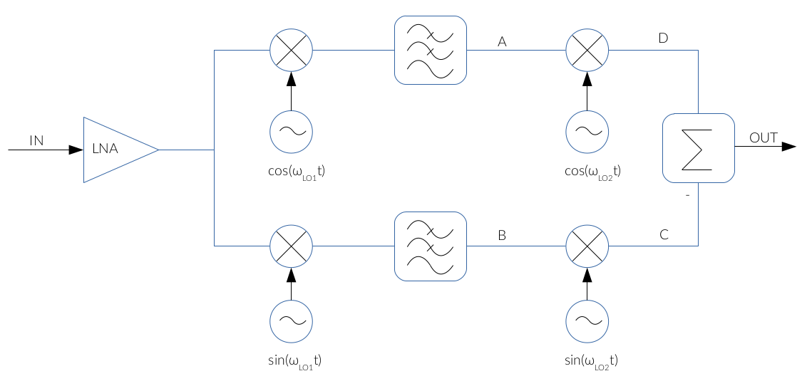
The implementation of the phase shifter in the Hartley architecture degrades the image rejection figure because of the impairments in the manufacturing process of the RC-CR network. In this sense, the Weaver architecture improves the Hartley structure by replacing the phase shifter by two mixers as shown below [1]:

Fig. 1: Weaver Image Rejection Mixer
The IF voltage waveforms at the points A and B are the same as in the analysis of the Hartley architecture, so:
$$ IF_A( t ) = { A_{SIG} \over 2 } · cos( (\omega_{SIG} - \omega_{LO1}) · t ) + { A_{IM} \over 2 } · cos( (\omega_{LO1} - \omega_{IM}) · t ) \tag{1} $$
$$ IF_B( t ) = -{ A_{SIG} \over 2 } · sin( (\omega_{SIG} - \omega_{LO1}) · t ) + { A_{IM} \over 2 } · sin( (\omega_{LO1} - \omega_{IM}) · t ) \tag{2} $$
As seen in the block diagram above, the previous signals are again downconverted using another LO frequency, fLO2, so:
$$ IF_C( t ) = { A_{SIG} \over 4} · cos( (\omega_{SIG} - \omega_{LO1} + \omega_{LO2}) · t) + { A_{SIG} \over 4} · cos( (\omega_{SIG} - \omega_{LO1} - \omega_{LO2}) · t) $$
$$ + { A_{IM} \over 4} · cos( (\omega_{LO1} - \omega_{IM} + \omega_{LO2}) · t) + { A_{IM} \over 4} · cos( (\omega_{LO1} - \omega_{IM} - \omega_{LO2}) · t) \tag{3} $$
$$ IF_D( t ) = { A_{SIG} \over 4} · cos( (\omega_{SIG} - \omega_{LO1} + \omega_{LO2}) · t) + { A_{SIG} \over 4} · cos( (\omega_{SIG} - \omega_{LO1} - \omega_{LO2}) · t) $$
$$ - { A_{IM} \over 4} · cos( (\omega_{LO1} - \omega_{IM} + \omega_{LO2}) · t) + { A_{IM} \over 4} · cos( (\omega_{LO1} - \omega_{IM} - \omega_{LO2}) · t) \tag{4} $$
Finally, the output is obtained by inverting IFD and adding it to IFC:
$$ IF_{OUT} ( t ) = { A_{SIG} \over 2} · cos( (\omega_{SIG} - \omega_{LO1} - \omega_{LO2}) · t ) + { A_{IM} \over 2} · cos( (\omega_{LO1} - \omega_{IM} - \omega_{LO2}) · t ) \tag{5} $$
Equation (5) shows that the spectral component coming from the image frequency is pushed to higher frequencies, so the desired signal is obtained after a low-pass filtering.
As mentioned before, the Weaver architecture reduce the impairments caused by the lumped components in the Hartley architecture. However, both signal paths must be as similar as possible to obtain a good image rejection.
Another counterpart of the Weaver architecture is that it suffers from the secondary images problem because it implements a two-step downconversion. This issue is covered in the secondary image post.
See also
References
[1] Supisa Lerstaveesin, An Image Rejection Circuit with Sign Detection Only, University of California, San Diego, 2006